NA

R23 Sem Exam Model Paper -PDF LINK
Previous Papers - R20 QP and Key - Link
R23 Syllabus for Network Analysis
Unit-1:
1.1 Types of circuit components
1.2 Types of Sources and Source Transformations
1.3 Mesh analysis and Nodal analysis
1.4 Principle of Duality
1.5 Impedance concept, phase angle, series R-L, R-C, R-L- C circuits, Complex impedance and phasor notation for R-L, R-C, R-L-C
1.6 problem solving using mesh and nodal analysis
1.7 Star-Delta conversion
Unit-2:
2.1 Network Theorems: Thevenin's Theorem
2.2 Norton's Theorem
2.3 Reciprocity Theorem
2.4 Compensation, Substitution Theorems
2.5 Superposition Theorem
2.6 Max Power Transfer Theorem
2.7 Laplace transform: introduction, Laplace transformation, basic theorems
Unit-3(1):
3.1 Transients: First order differential equations, Definition of time constants, R-L circuit
3.2 R-C circuit with DC excitation, evaluating initial conditions procedure
3.3 problem solving
3.4 second order differential equations, homogeneous, non-homogenous, problem-solving using R-L-C elements with DC excitation and AC excitation,
3.5 Response as related to s-plane rotation of roots.
Unit-4:
4.1 Resonance: Introduction, Definition of Q, Series resonance,
4.2 Bandwidth of series resonance
4.3 Parallel resonance and general case-resistance present in both branches, anti-resonance at all frequencies.
4.4 problem solving
4.5 Coupled Circuits: Self-inductance, Mutual inductance, Coefficient of coupling
4.6 analysis of coupled circuits, Natural current, Dot rule of coupled circuits, conductively coupled equivalent circuits
Unit-5: Assignment Key
5.1 Two-port: Relationship of two port networks, Z-parameters
5.2 Y-parameters
5.3 ABCD- parameters
5.4 hybrid parameters
5.4 h- parameters
5.5 Relationships Between parameter Sets
5.6 Parallel, series, cascading of two port networks
5.7 problem solving
5.8 Image and iterative impedances (Qualitative treatment only)
Text Books/ Web References
1. Network Analysis - ME Van Valkenburg, Prentice Hall of India, revised 3rd Edition, 2019.
2. Engineering Circuit Analysis -WilliamH. Hayt, Jack Kemmerly, Jamie Phillips, Steven M. Durbin, 9E
PDF Text Books
1. Engineering Circuit Analysis by Hayt PDF LINK
2. Network Analysis by Sudhakar and Shyammohan PDF LINK
Web References:
NPTEL Course Link
NA Model Problems
KVL model1
KVL model2
KVL model3
KCL model1
KCL Model2
KCL model3
Mesh model1
Mesh model2
Mesh model3
Mesh model4 (Super Mesh)
Mesh model5 (Super Mesh)
Mesh model6 (Super Mesh)
Nodal model1
Nodal model2
Nodal model3
Nodal model4 (Super Node)
Nodal model5 (Super Node)
Duality model1
Duality Model2
Source Transformation model1
Source Transformation model2
Standard AC Signal Waveforms (useful for unit-3)


Material Unit-1: R, L, C- Series and Parallel; KVL and Mesh, KCL and Nodal; Steady State;
single node (two ore more loops) ----> then use KCL
two or more loops -----> then use Mesh Analysis
two or more nodes -----> then use Nodal Analysis


Use of Mesh equations for each loop. If there are 4 loops from left to right.
Then Apply Mesh Analysis (similar to KVL) for the loops as follows:
Mesh for loop1
Mesh for loop2
Mesh for loop3
Mesh for loop4

Nodal Equation for node1
Nodal Equation for node2

- Series elements become parallel elements between nodes and vice-versa
- horizontal elements become vertical elements between nodes and vice-versa
Source Transformation:

--------------------------
--------------------------


Quiz Unit-1

Assignment Questions Unit-1


Assignment Key Unit-1
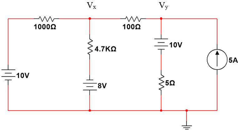
Assume clockwise current I.
Apply KVL:
-13+200I+4700 I+ 3+470 I+330 I+ 10000 I=0
15700 I = 10
I= 0.000636942 A = 636.942µA


4.


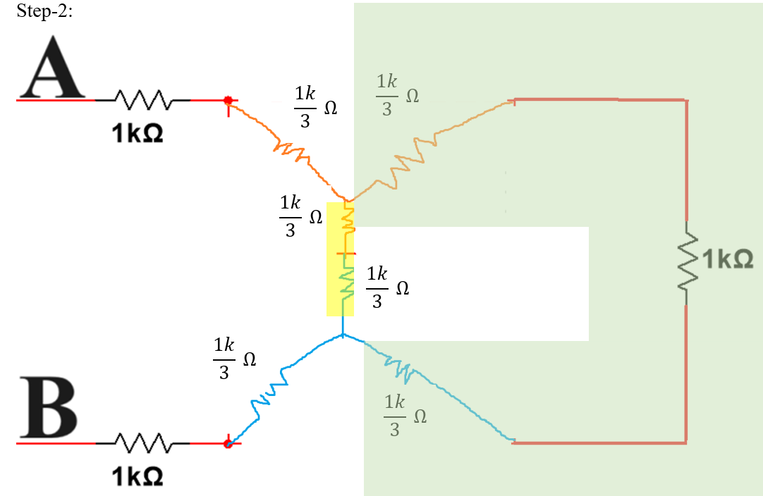
step-2: connect each node inside loop and ref_node via elements in that loop only. replace the elements with their dual element.
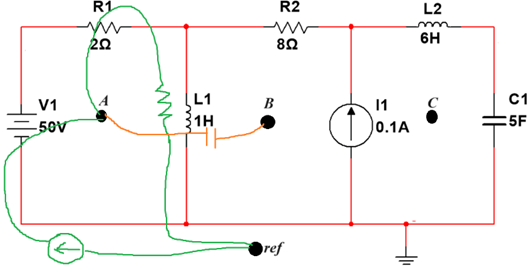
step-3: continue the step2 for nodes inside remaining loops also.

Step-4: draw the final dual figure

Mesh analysis:


before solving mesh/nodal here all the inductors/capacitors must be replaced with their reactance values respectively.


STEP-4:
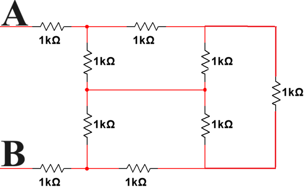
ANS: 22000/7 = 3142.857Ω = 3.143kΩ
Material Unit-2: Network Theorems, L.T, I.L.T and Partial Fractions


Quiz Unit-2
Assignment Questions Unit-2


Assignment Key Unit-2
.png)
.png)
.png)
.png)
.png)
.png)
.png)

.png)
.png)
.png)
.png)
Material Unit-3: Transients
A loop if contains only L or only C is first order circuit; if a loop contains both L and C = second order circuits.
Example: RC circuit is 1st order; RL circuit is 1st order circuit; RLC is a 2nd order circuit;
Topics:
1. Initial Conditions
2. Revise topics L.T, I.L.T, Partial Fractions in Unit-2 Part-2
3. DC (step) excited circuits - RC, RL, RLC : here to calculate time constant(𝜏) i(t), v(t), etc.,
4. AC (Impulse, Ramp, Sine, Cosine) excited circuits - RC, RL, RLC : here to calculate i(t), v(t), etc.,
5. di/dt , d^2i/dt^2 problem solving

element | t=0+ | t=∞ |
R- Resistor | R | R |
L- Inductor | open circuit | short circuit |
C- Capacitor | short circuit | open circuit |


Quiz Unit-3
1. For the given circuit, the switch is closed at t=0; Assuming zero initial conditions, current through inductor at i(0+) = ______ amperes


3. For the given I(s), i(t) = _______ A

4. Laplace transform of Inductor of 2mH is _____
5. Laplace transform of Capacitor of 1uF is _____
6. Laplace transform of source Vs = 20 V is ______
7. Laplace transform of source di(t)/dt is ______
8. Laplace transform of source ∫i(t) dt is ______
Q 9, 10 are linked answer Questions:
9. for the given circuit, KVL is _____________

10. for the above KVL , Laplace transform is __________________
Answers:
1. i(0+) =0 A
2. 0.2 e-200t A
3. 2 e-3t - 4
e-2t A
4. 2x 10⁻³ s
5. 1x 10⁻⁶ / s
6. 20 /s
7. s I(s) - i(0)
8. I(s) /s
9.
![]()
10.
Assignment Questions Unit-3


Assignment Key Unit-3
1. Compare Steady state analysis and Transient analysis.
3. Determine the time constant of a series R-L network with DC excitation.
use similar approach followed in Q2.
4. use figure-3.1; Determine the inductor voltage for t >0.

t<0 --> After a long time with switch at this position, Inductor acts as S.C; 10V appears across 4Ω resistor. So current I4Ω = 10/4 =2.5A = iL
at t=0 switch is moved ---> voltage source disconnected at top terminal; So it experienced O.C.
As inductor does not allow sudden changes in current, iL(0+) =2.5A
Applying KVL, 10iL+v= 0 ---(1);
Also v=5diL/dt ---(2);
substitute (2) in (1) --> 10iL + 5diL/dt = 0 ---(3)
applying Laplace Transform for Eq(3):
10 I(s) + 5 [sI(s)-i(0)] =0
10 I(s) + 5[sI(s)-2.5]=0
2 I(s) + [sI(s)-2.5] =0
I(s) [2+s] = 2.5
I(s) = 2.5/ (s+2)
Applying Inverse Laplace Transform to I(s):
L-1{2.5/(s+2)} --->
i(t) = 2.5 e-2t ----(4)
substitute (4) in (2) ---->
5. For figure-3.2, Also the switch is open for a long time and closed at t=0. Determine di1(t)/dt, di2(t)/dt at t=0+.

figure-3.2
until t<0 ---> i2H(0-) = 0A
i5H(0-) = 0A because there is no source in the second loop.
as inductor does not allow sudden changes in current, i1(0+)=0A, i2(0+)=0A

6. use figure-3.3; Determine v(t) at t=0 and t=160µs
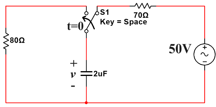
figure-3.3
Before the switch moves (t<0), the 80Ω resistor is not connected completely (i.e., i=0. Also Assuming that switch position there from long time i.e., capacitor fully charges and there is no path for discharge.
So, v(0-)= 50 V
switch position is changed at t=0; As capacitor cannot discharge instantly (capacitor does not allow sudden changes in voltage), v(0+) =50V
now the new circuit is RC network.
time constant is τ=RC = 80 x 2µ = 160µs
voltage across capacitor is, v(t) = v(0) e-t/τ
---> v(t) = 50 e-t/(160µ) Volts ----(1)
(a) v(0) ---> t=0 in equation(1) ---> 50 e0 = 50 volts
(b) v(160µs) = 50 e-(160µ)/(160µ) = 50 x e-1 = 18.3939V
i1(0+) =1A
i2(0+)=0A
di1/dt at t=0+ = -4990 A/s
di2/dt at t=0+ = 10A/s
d2i1/dt2 at t=0+ =24899900 A/s2
d2i2/dt2 at t=0+ = -50100 A/s2

Material Unit-4: Resonance and Coupled Circuits
Topics:
1. Resonance:
(a) Series Resonance (ωo, ω2, ω1, BW, Q)
(b) Parallel Resonance (ωo, ω2, ω1, BW, Q)
(c) Parallel Resonance with internal resistances (ωo only)
2. Self Inductance(L), Mutual Inductance (M), Coefficient of Coupling (k)
3. Natural Current
4. Dot rule
5. Conductively coupled circuits
6. Problems on dot rule directly; Mesh analysis based problems


Quiz Unit-4
1. Formula for Quality factor is ______
2. Fill the below table with appropriate formula:
Parameter | Series Resonance (Series RLC) | Parallel Resonance | ||
Simple R L C parallel | LC Parallel (Only inductor has internal resistance) | LC Parallel (Both Capacitor and inductor have internal resistances) | ||
Resonant frequency = ωo | | | | |
Answers:
1. Q= resonant_frequency / Bandwidth = ωo / (ω2 – ω1) OR fo / (f2 – f1)
2.

Assignment Questions Unit-4


Assignment Key Unit-4
Q1.
Material Unit-5: Two Port Networks
Topics:
1. Z, Y, ABCD, hybrid parameters
2. Conversion of network parameters
3. Series, Parallel and Cascading of two 2-port networks
4. Image Impedance and Iterative Impedance


 |
| Zt1=Zt2 as they are iterative impedances |
Quiz Unit-5
1. In the space provided, mention whether the below statement is True/ False.
If two two-port networks (Say X, Y) are connected parallel, then voltages across same end ports of the two networks is same.
2. In the network given below, with I2=0. The value of Ib = ______, V2 = _______

Questions 3,4,5,6:
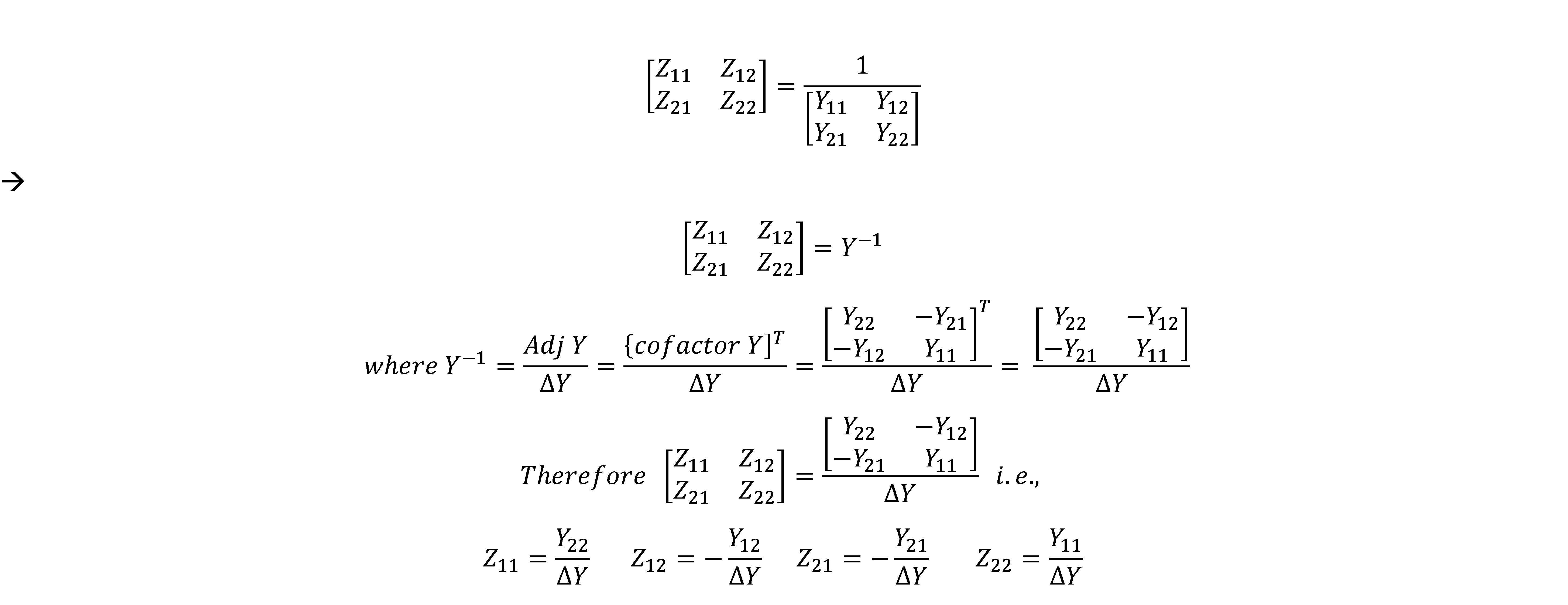
For the given network below, Z11 = ______, Z21 = ______, Z22 = ______, Z12= _____

Questions 7,8,9,10:
For the network below, the value of Y11 = ____, Y21 = ____, Y22 = ____, Y12= ___

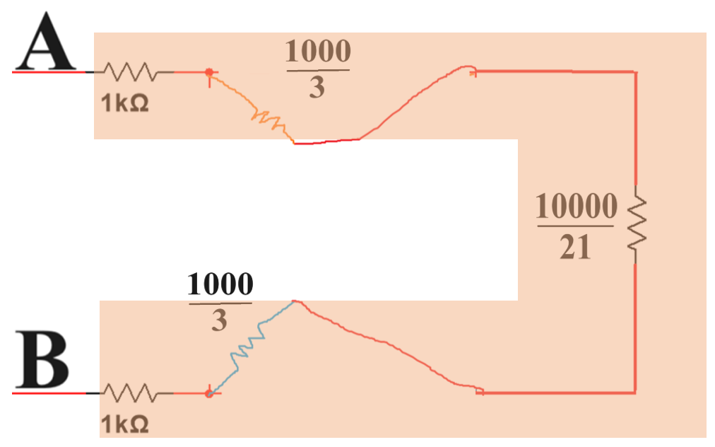
11,12,13,14. For the network below, the value of Y11 = ____, Y21 = ____, Y22 = ____, Y12= ___

Answers:
1. True
2.

3, 4, 5, 6.
Z11 = 8+5=13 ohms
Z21= 5 ohms
Z22 =7+5 =12 ohms
Z12 =5 ohms
7, 8, 9, 10.
Y11 = 3/2 mhos
Y21 = -1 mhos
Y22 = 4/3 mhos
Y12 = -1 mhos
11, 12, 13, 14:
KCL at V1:
-I1 + V1 (2) + (V1-V2) 1 =0
--> I1 = 3V1 -V2
Y11 = 3℧, Y12= -1℧
similarly
-I2 + V2 (3) + (V2-V1)1 =0
-->
Y21 = -1℧, Y22= 4℧
Assignment Questions Unit-5


Assignment Key Unit-5


Important points that repeat in every unit
---Steady State (units- 1,2,4,5)-----
Ohms Law= Voltage at resistor= V= IR
Voltage at inductor = V= I (jωL)
Voltage at capacitor = V = I [-j/(ωC)]
-----------------------
---Transients (unit-3)-----
Ohms Law= Voltage at resistor= V= i(t) R
Voltage at inductor = V= L di(t)/dt
Voltage at capacitor = V = (1/C) ∫ i(t) dt
-----------------------
k=kilo = 103
M=Mega= 106
G=Giga= 109
T =Tera= 1012
m= milli= 10-3
μ = micro= 10-6
n= nano= 10-9
p= pico= 10-12
-------------------------
Vab = Va - Vb
GATE/ NET Exam info
GATE 2023:
Circuit Analysis:
GATE Pattern for ECE:
Marks (Questions)= 100M (65Q) = 15M (10Q on GA) + 85M (55Q on EC)
NOTE: 15M for GA + (12 to 15M for Engg Maths) +( 73 to 70M for EC)
Questions pattern= MCQ, MSQ, NA
Negative marking = Mark/3; Example: if its 2M question, then negative marking is 2/3.
NOTE: Negative marking for MCQ only.